When I first started this blog, I wrote a post on tuft
testing which turned out to be one of the more popular articles here. I
covered the basics of tuft testing but recently thought I could write a little
more about how to interpret tuft behavior and what this looks like in the real world. This article will demonstrate
how to set up a tuft testing session, how to get usable results, and how to start analyzing them.
Setup
As I wrote before, tuft testing is cheap and easy; all you need
is yarn, tape, and a camera.
Your tufts shouldn’t be too short (they won’t show up well
on camera) or too long (long, flapping tufts will give you less resolution in
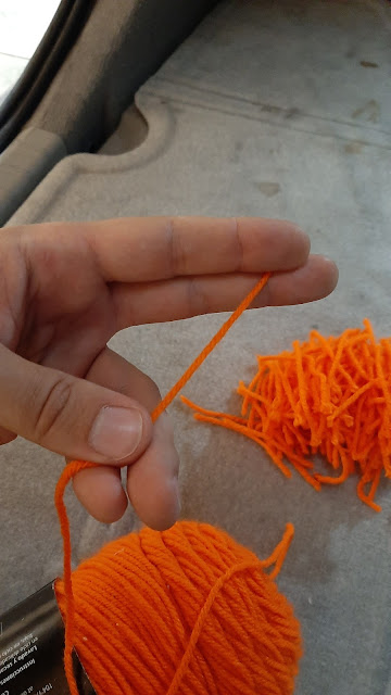
the airflow patterns). I like to hold a length of string between my second and
third fingers, stretch it across my hand, and then cut it near the thumb:
This gives me pretty consistent 60-70mm tufts—long enough to
be visible to a camera some distance away.
Once you have your tufts cut, tape them to your car. You can
use long strips of tape with evenly spaced tufts or tape each one individually.
Keep the tufts far enough apart that they won’t get tangled with each other,
especially in areas where you suspect the flow will be separated and the tufts
might flap around a lot.
I start by laying out a line of tufts in one direction:
Then, I put down another line normal to the first:
Finally, I fill in the grid:
Of course, this works better on some panels (flat, rectangular)
than others (curved, irregular outlines) but it’s a good starting point for an
ordered, methodical arrangement of tufts. You don’t have to do it this way;
just ensure that your car has enough tufts to see what you want to see.
On the Road
Enlist the help of a friend to drive your car (thanks Nathan!) or to use a
camera while you drive. You don’t need a high-end camera or
fancy setup; a cellphone camera that will take pictures in Burst Mode is
perfectly adequate. On Samsung phones, slide the shutter button to the right
and hold it to activate Burst Mode; the camera will take up to 30 pictures over
just a few seconds. While the car drives by, follow it with the camera and you
should end up with a series of clear photos showing the tufts. Download them to
your computer and scan through them, looking at any changes in the tufts over
time (even in areas of attached flow, there will be some movement of the tufts
due to turbulence). Choose the most representative photos
for further analysis.
You might be interested in getting a snapshot of the flow
over your car as it is, but you could also try changing some things to see what
happens to the tufts. In this session, I first took photos of the car as I’ve
been driving it (modified from stock); then, I blocked my external air curtain
ducts, added the fins I’ve tested before, and threw on a bumper bar
light mount since I’ve been considering adding some extra lighting before my
road trip through the Southwest later this summer.
What can you learn from a tuft test? Lots.
Analysis
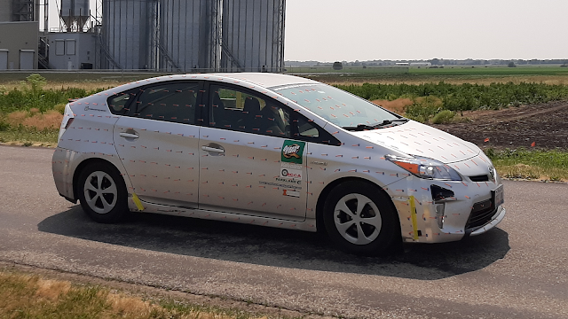
Test #1: Standard configuration
By “standard” I mean the car as it sits—modifications from
stock include 40mm lower ride height, larger front wheel spoilers, external air
curtain ducts, external engine air intake, mirrors/rear wiper/antenna removed, small lip spoiler, underbody
exhaust tunnel closeout panel, and extended rear diffuser panel with vertical
strakes.
How about that—overall, the flow is exactly what we want to
see, and a testament to how well Toyota engineers did their job during the development
of this car. Most cars will have areas of separation, even late-model cars;
common problem areas include the windshield around the wipers, the side windows
behind the A-pillars, the side body behind the wheel openings, and the lower
part of the rear glass, especially on sedans. On this Prius, there is very
little separation behind the wipers, very little disruption at the A-pillars, no
separation behind wheel openings, and attached flow all the way down the rear
glass and across the stock and add-on spoilers. Attached flow from front to
back is exactly what we want on our cars for low drag (that is, the car body is
streamlined—it doesn’t suffer from areas of separation), and this
car looks better than I expected.
That said, there are a few curiosities. Notice the tufts on
the front splitter—they don’t point back, toward the cooling air opening, but forward
and wrap under the car.
At the rear, the tufts taped to the diffuser extension show
that air is blowing backward out of it, but outside of the strakes and behind
the muffler, they’re pointing forward. These stand out
as areas I might be able to improve, perhaps by rerouting the exhaust and
fitting paneling or building an extended or sharper front splitter.
Test #2: Blocked air curtain ducts
In standard configuration, the tufts show air flowing into
my air curtain ducts as I intended. The rear duct has attached flow over its
outside surface, while the front duct has some separation on its
outside middle.
With the duct inlets taped, a recirculation bubble forms in
front of what was the opening. Further, flow now separates completely across
the outside surface of both front and rear ducts. Curiously, the flow on the
body after the wheels doesn’t appear to be affected much (there's a little separation right behind each opening); this compares well with the
pressure measurements I made with the ducts removed completely, which showed no
change in pressure behind the front wheel openings and only a slight rise in
pressure (+10 Pa at 50 mph) behind the rears with ducts fitted.
Test #3: Rear fins
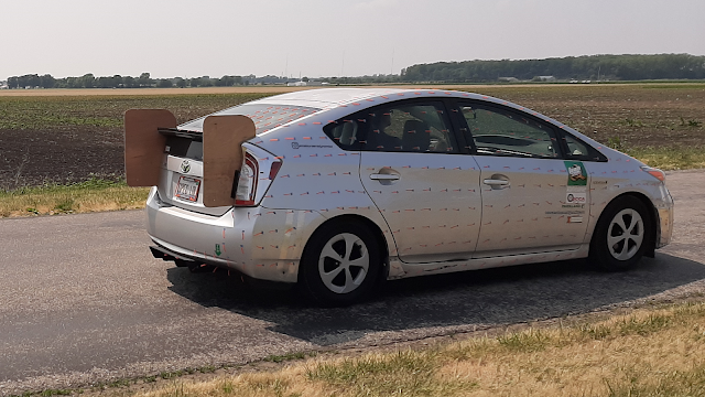
Just for fun, I threw on the fins I’ve been testing to
improve straight-line stability (I didn’t bother with the crossbar brace since
this testing was done at low speed—35 mph—and in light winds).
Interestingly, the fins don’t change the flow pattern on the
upper body as I thought they might. Instead, take a look at the tufts behind
the muffler:
Surprisingly, fitting fins to the upper body looks to be changing
the flow under the body. This is the kind of interaction you will be
very, very unlikely to predict; I had no idea I would find this and it
warrants further investigation.
Test #4: Bumper bar light mount
Finally, I attached the light mount. The upper part of this mount is a horizontal flat plate that looks like it should massively disrupt flow across the front of
the car.
But it doesn’t. The tuft immediately above the mount shows
separation, but above the emblem the flow looks the same as before. This mount
might affect flow into the cooling air openings, though, so I’ll plan on
measuring pressures across the cooling package before I make any decision about
installing it permanently with lights.
Don’t Guess, Test
Try it yourself, on your own car!


Comments
Post a Comment